Front panel cable for Supermicro SC512L chassis to a Via EPIA M10000 motherboard
The Supermicro chassis comes with a 16 way straight through cable from the front panel to the motherboard. The layout for this is not pin for pin compatible with a EPIA M10000 motherboard. This document describes a hand made replacement cable.
The Supermicro SC512L chassis comes with a front panel with a FP512 v3.0 front panel board.

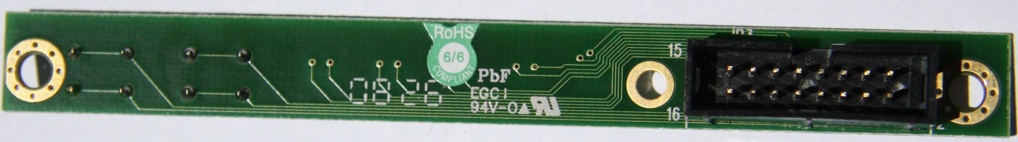
This board provides:
- a power button
- a reset button
- a power LED
- a disk activity LED
- two NIC LEDS
- a fault LED
The EPIA M10000 motherboard can directly utilise the power/reset buttons, the power LED, and the disk activity LED. I chose to wire the 'stand-by' LED functionality onto the fault LED. The EPIA motherboard provides no headers for driving NIC LED's. Both NIC LEDS are not used.
Cable
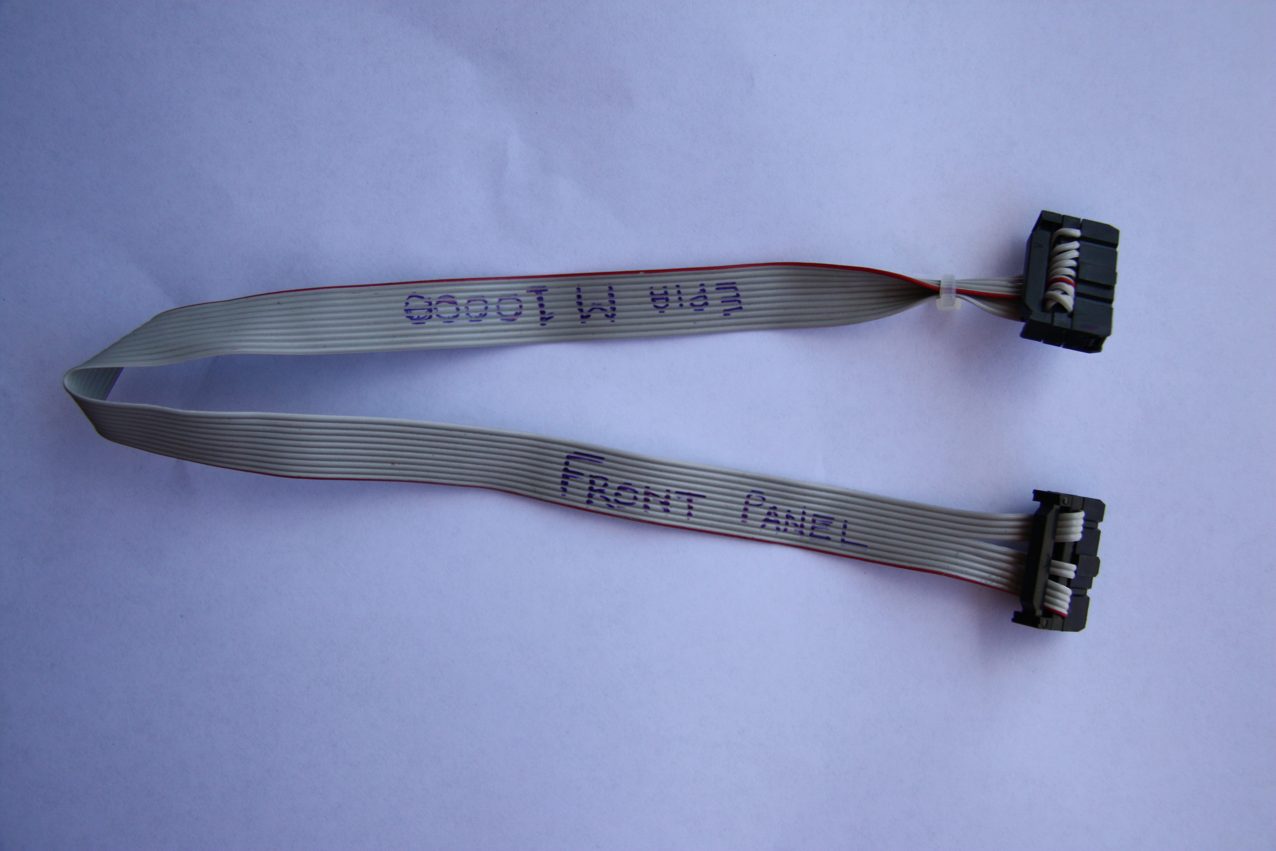
Construct the cable using a short length of ribbon cable and two 16 pin IDC headers (with strain relief).
| Signal function | Supermicro FP512 Front Panel PCB pin |
EPIA M10000 fp_panel header pin |
|---|---|---|
| Power switch |
1 | 6 |
| Power switch (Ground) |
2 | 8 |
| Reset switch |
3 | 10 |
| Reset switch (Ground) |
4 | 12 |
| Standby LED |
7 | 14 |
| Standby LED |
8 | 16 |
| HDD LED |
13 | 2 |
| HDD LED |
14 | 4 |
| Power LED |
15 | 3 |
| Power LED |
16 | 5 |
The completed cable:
Links
- http://www.supermicro.com/products/chassis/1U/512/SC512L-260.cfm
- http://www.via.com.tw/en/products/mainboards/motherboards.jsp?motherboard_id=81
Appendices
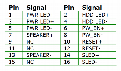
EPIA M10000 header pins
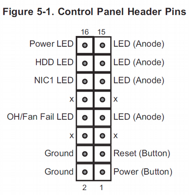
SC512L front panel header pins
Note: The FP512 REV 3.0 PCB assembly supports two NIC LEDS. The second NIC uses the pins 9 and 10, which are marked as 'x' in the diagram below.