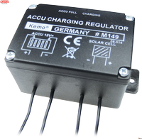
Kemo Electronic - Solar charging controller 12v DC, 6A (M149)
|
Solar charging controller 12 V/DC, 6 A [M149]
|
|||||||||||||||||
This solar charging controller is connected between a solar cell 12 V/DC (open circuit voltage 14 - 30 V/DC) and an accumulator 12 V/DC to prevent an overcharge of the accumulator. LED displays for "accu full" (approx. 14,4 V/DC) and "charging". Own power consumption < 2,5 mA. |
Circuit description:
This module is an electronic switch which switches on the connection to the solar cells if the accumulator is empty and switches off again when the accumulator is fully charged. A power MOS transistor that switches almost lossfree is used as circuit element.
Intended use:
Charge control for 12 V accumulators by means of solar cells up to max. 6 A.
Mounting instructions:
The module is to be mounted as close as possible to the accumulator or groups of accumulators, respectively, to be charged (ideal: max. 50 cm). The cross section of the cable between the charging controller and accumulator should be at least 1,5 qmm.
Reasons: If the cable is longer or has a smaller cross section, respectively, the measuring result of the battery voltage measurement will be changed due to the higher internal resistance of the cable. This will neither damage the accumulator nor the charging controller, but it causes a frequent charging interruption because a higher voltage is measured due to the additional line resistances and the smaller proximity to the solar cell, and the charging controller switches off earlier.
The cable towards the solar cells may be of any length. The following applies here: The longer the cable, the higher the line loss. The energy yield will be reduced this way. So you should lead the cable to the charging controller the shortest possible way and use cable which is not too thin (0.75 qmm are sufficient, better are 1.5 qmm).
Important: Do only connect solar cells up to a power of 60 W as current source! Do not use stronger current sources and no transformers, battery chargers, accumulators, wind wheels, etc.
Important: Connect a safety fuse 10 A in the lead between the accumulator and charging controller (not enclosed)!
Setting into operation:
After wiring everything according to the drawing and description, the device is ready for operation. When the accumulator is
being charged the LED “Charging” lights up. If the accumulator is fully charged, the LED “Accu full” lights up. If the accumulator
is empty (< 13.4 V) and is not being charged (the solar cell does not work, perhaps no solar radiation), no LED will light up.
Technical data:
- Input voltage: solar cell panels: 14 - 30 V/DC open circuit voltage, nominal voltage: 12 V/DC
- Max. input current: 6 A, shorttime till 5 min: 10 A |
- Inrush voltage: battery voltage < approx. 13,4 V
- Interrupting voltage: battery voltage > approx. 14,4 V
- Displays: 1 LED for “Charging”, 1 LED for “Accu full”
- Own power consumption: < 2,5 mA (LED switched on)
- Dimensions: approx. 72 x 50 x 42 mm (without fixing straps)
Links
- M149-Solar-charging-controller-12-V-DC-6-A
- Datasheet (cache)
- Frizzell Ltd - Solar Chargers
- M149 from Jaycar


